NOTE: Perform this operation at your own risk! This requires very strong skills in
mechancial and electroincs repair.
Before removing the instrumet cluster from the vehicle, make sure the ignition
is switch off and the key remove, or you may generate an SRS error that may
require visiting an authorized service center to repair.
You will need a
tool to remove the cluster from the dash.
Mercedes-Benz makes an official tool, and some people will claim that
you must use the OEM tool or risk damaging your vehicle. The reality is, once you see what you are doing,
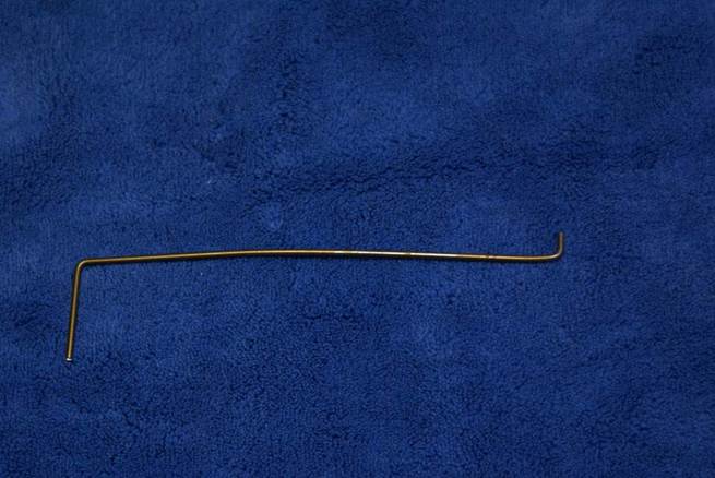
you will understand why it’s not really that critical. I use a stiff piece of wire (cut from a
coathanger), bent as shown. The working
end is the small end and it’s about 3/8 of an inch long. It’s about 6 inches in length, and the other
end is just over an inch, and is the handle.
Insert the tool into the slot in
the cluster until to contacts the locking mechanism.
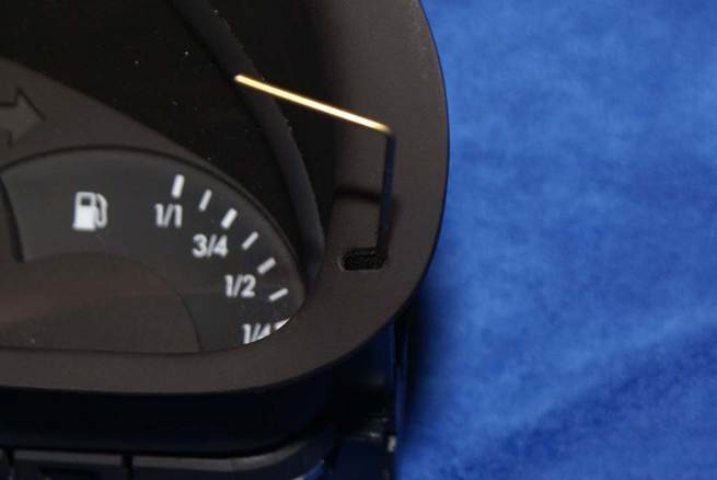
The locking mechanism grips the
dash on the bottom of the cluster. Just
rotate the tool slightly and continue pressing in to move the release upward
and thus allow the cluster be release form the dash. You have to do this on both sides, so you
might want to make two tools and use them simultaneously (though you can use
just one tool and release one side at a time).
Once the cluster locks are
released, remove the unit from them dash and disconnect the electrical connector. It has a locking lever that must be lifted up
and then the connector can be unplugged and the cluster removed from the
vehicle.
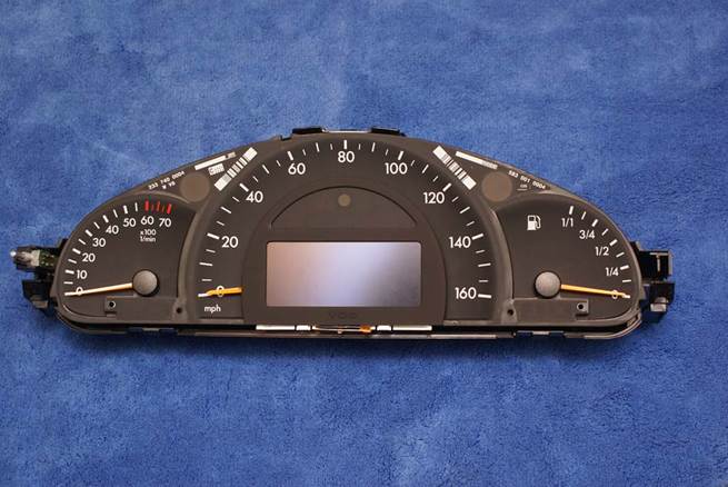
To disassemble the cluster, there
are five plastic tabs, three on to and two on the bottom,
that must be released. You can use
your fingers, a screwdriver, or a plastic tool to gently release the tabs and
pull the cluster apart.
Once
the tabs are released, remove the clear lens part of the cluster assembly.
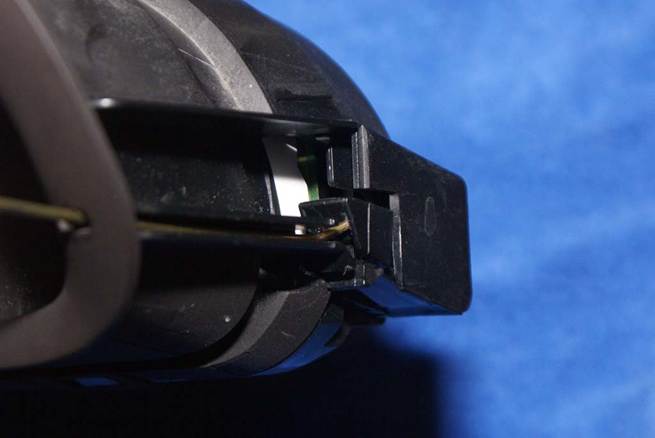
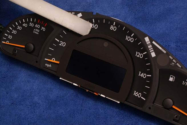
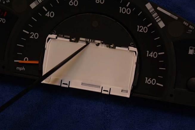
Now you need to remove the bezel
that covers the LCD display. Pry outward
on it as shown on the top.
Once the bezel is removed, you will
see that the LCD panel is held in place by the plastic clips on the white
surround.
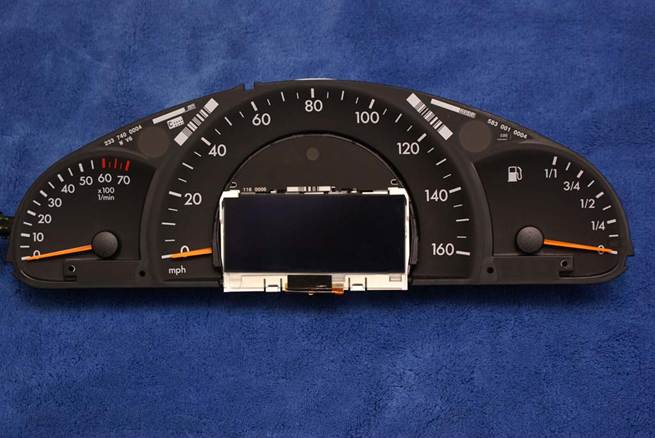
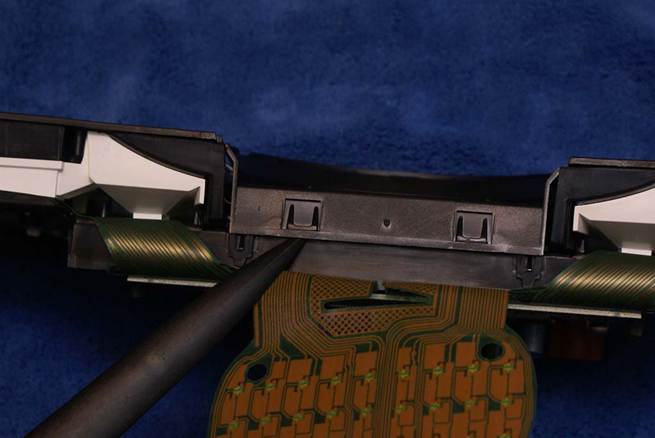
Before removing the LCD panel, you
need to disconnect its electrical connection.
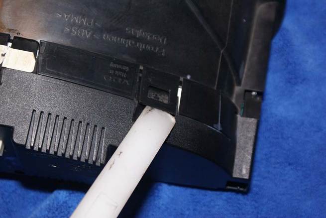
Turn the cluster over to the back.
Press on the outer edges of the brown locking bar as shown to move it
away from the connector.
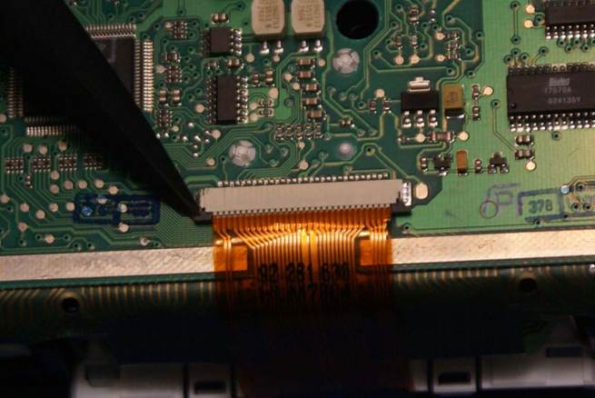
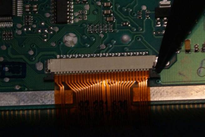
Once the brown locking bar has been
release, the ribbon cable can be pulled out of the connector.
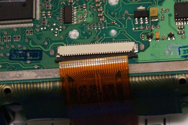
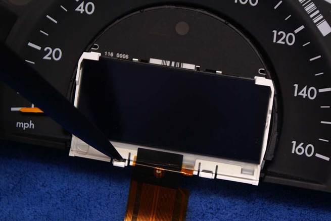
With the ribbon cable disconnected,
you can remove the LCD panel. Pry
between the white plastic clips at the bottom of the panel to release it.
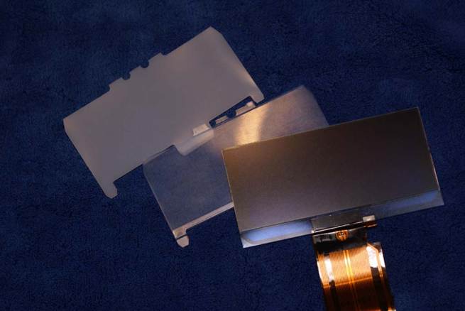
Once the LCD panel has been
removed, you now need to remove diffuser and the lens.
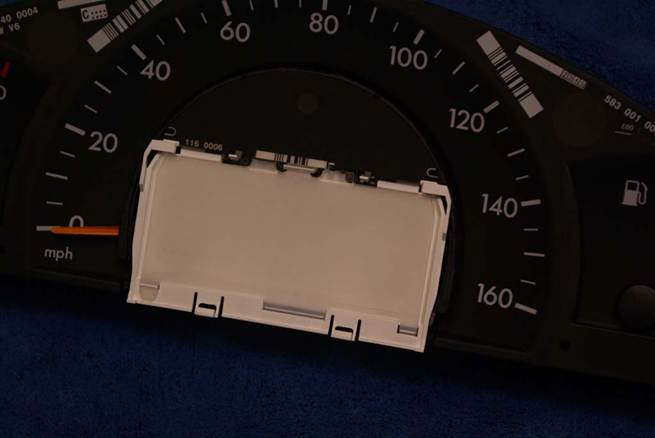
Pry on the plastic clip at the top
of these pieces to release them.
Shown in order of assembly (bottom
to top), you have the diffuser, the lens and the LCD panel:
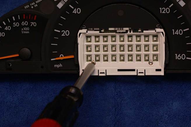
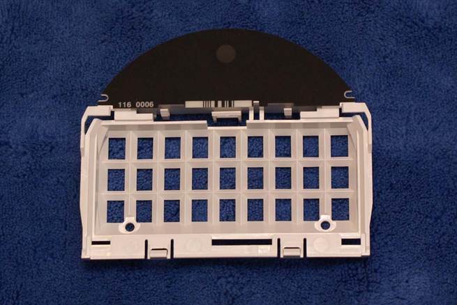
Next, the plastic holder for he LCD
panel needs to be removed.
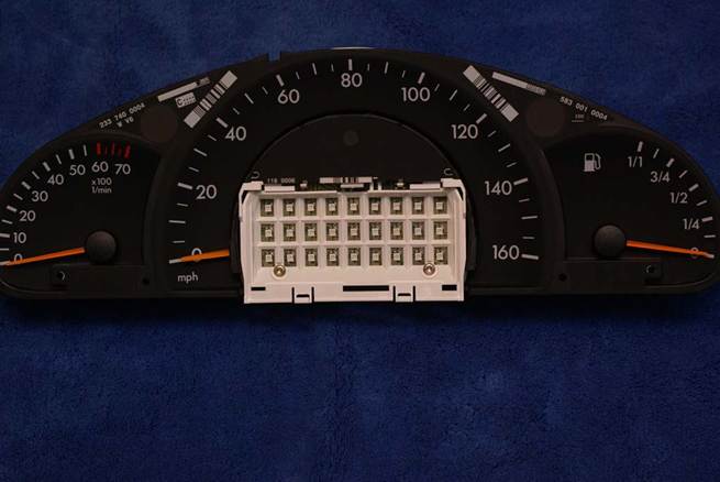
Use a T10 Torx
driver to remove the two screws holding the plastic holder in place.
After the two screws are removed,
the plastic LCD display holder can be removed from the cluster:
Next, remove the Mylar circuit
board that contains the LED’s away from the speedometer face. It is held in place by snapping onto two plastic
studs. Pry gently and it will come
loose.
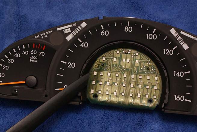
Fold the Mylar circuit board down
out of the wat to expose the speedometer cover.
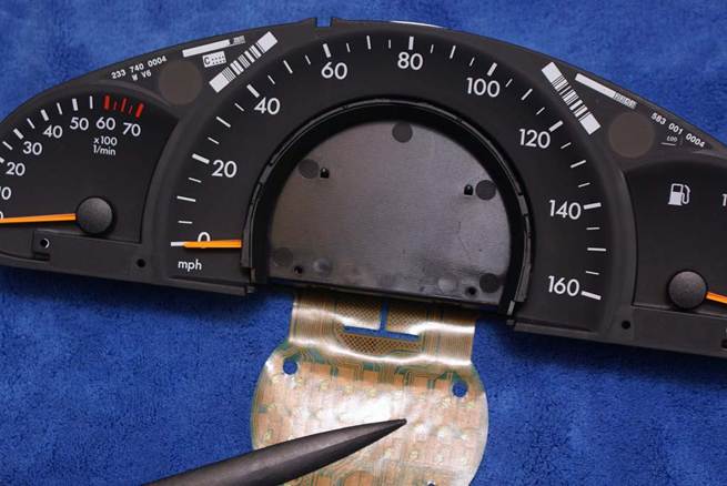
Remove the speedometer cover by
prying on the two plastic tabs on its bottom edge.
The speedometer cover shown removed
from the cluster:
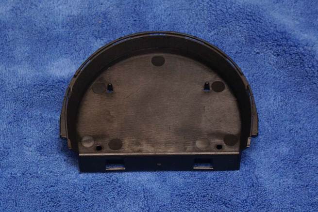
You can now see the speedometer
needle attached to the servo.
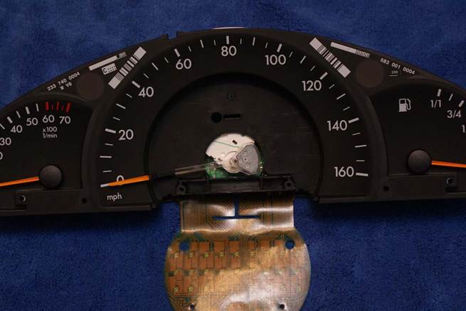
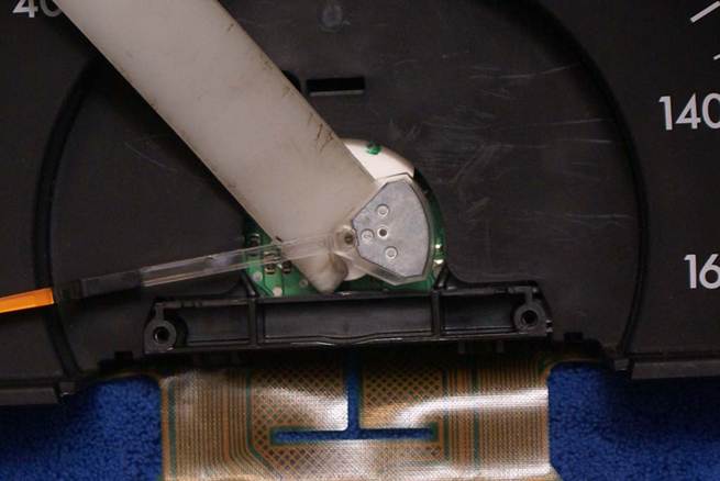
Remove the needle by prying gently
from behind.
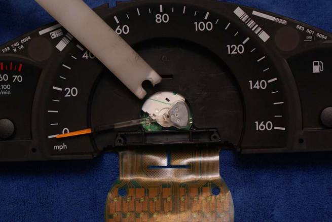
Be sure to pry against the servo so
that it does not come apart.
Turn the cluster over and now you
can remove the circuit board by release the two plastic clips holding it on
either side.
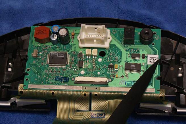
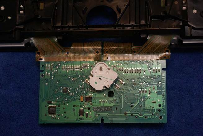
Fold the circuit board down to
reveal the speedometer servo.
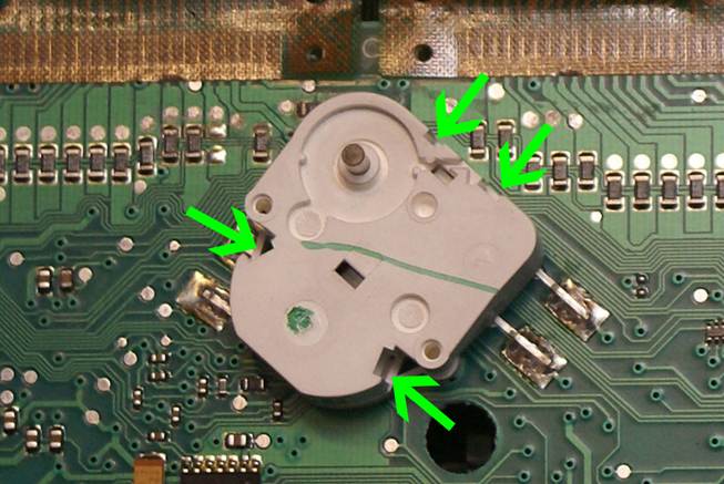
To remove the cover on the servo,
you will need to first shave the melted plastic heads from the two suds as shown.
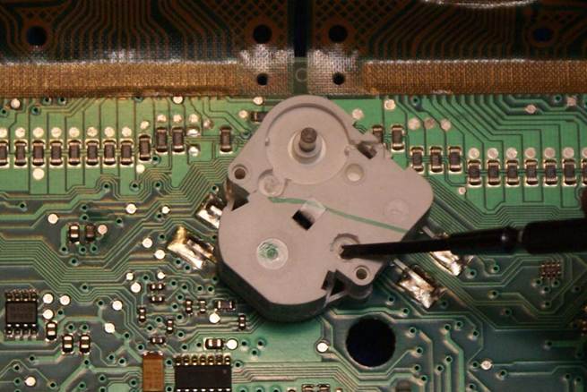
A small flat head “micro”
screwdriver works well for this. Just
scrape the melted plastic away.
Once the studs are broken loose,
you will need to pry very gently on the four retaining clips to release
them. Generally, you can pry on them one
at a time with a small screwdriver while lifting on the house and it will come
apart.
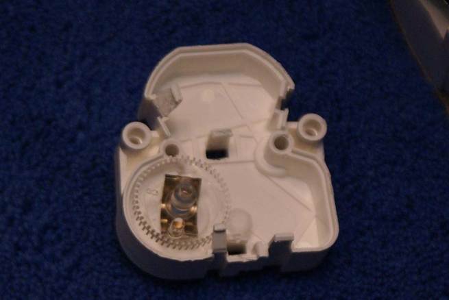
Gently remove the servo cover from
the circuit board. The main gear may
come off with the cover.
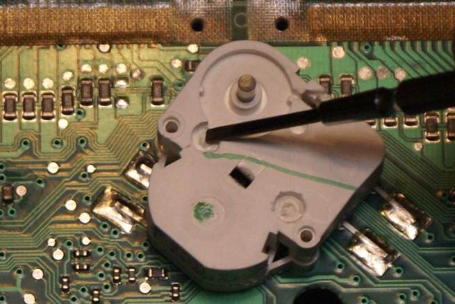
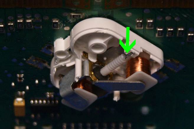
Make sure that the servo worm gear
is in place. Its shaft sits loosely in a
slot in the plastic housing as shown.
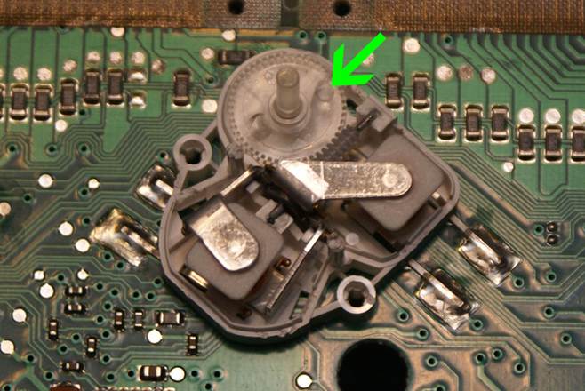
Remove the main drive gear from the
servo cover and place it into the servo housing. There is a small stud on the bottom of it
that is a stop for the needle sweep.
Place it as shown, which is just clockwise forward of
the plastic stop in the servo housing.
Now, snap the cover back onto the
servo. Fold the circuit board back over
the cluster housing and snap it into place.
Reinstall the cluster in the vehicle and connect the electrical
connection. You will need to switch on
the ignition to allow the system to self-calibrate BEFORE installing the speedometer
needle. If the speedometer servo “clicks”,
this means that the main gear is not properly installed. Immediately turn the ignition off, and remove
the cluster and reset the main gear as shown above. If the servo does not click, then you can now
install the speedometer needle, being careful to place it in the 0mph position,
without turning the servo. Switch the
ignition off and back on one more time to verify that the speedometer needle is
in the proper position.
Now, switch the ignition off,
remove the key (again, DO NOT disconnect the cluster unless the ignition is off
or it WILL create an SRS error). Remove
the cluster and reassemble it following the above steps backward:
Snap the speedometer cover back in
place.
Place the Mylar circuit board back
in place on the studs on the speedometer cover.
Place the LCD display holder back
in place and attach it with its two screws.
Insert the diffuser, then the lens,
into the LCD display holder.
Place the LCD panel in the holder,
top edge first. Gently press it toward
its top edge to allow it to snap into the clips on the bottom edge.
Insert the LCD’s ribbon cable into
its connector on the back of the cluster, then snap
the brown retaining clip back into place.
Place the bezel on the LCD panel, bottom
edge first then snap the top edge into its clips.
Place the cluster into the bottom
half of its housing, then snap the top “lens” half onto it, making sure all
five plastic clips lineup properly and snap into place.
Reinstall the cluster in the vehicle
by connecting the electrical cable and then pressing it firmly back into the
dash opening until the retaining snap into place and it is held securely.